Liquid Pressure Amplification
a Floating Head Pressure Technology, HY-SAVE
Liquid Pressure Amplification (LPA)
A Floating Head Pressures Technology without a loss in TEV or
EEV Capacity: Becker/O’Brien, 2008, UK
Definitions
EEV = Electronic Expansion Valve.
TEV = Thermostatic Expansion Valve.
As head pressure is dropped:
The compressor would tend to unload because:
As head pressure is dropped
The compressor would tend to unload because:
- Liquid temperature hence liquid enthalpy reduces giving increased specific refrigeration effect allowing a reduction in mass flow.
- Compressors swept volume would increase due to increased volumetric efficiency brought about by reduced compression ratio (Clearance Pocket). The compressor would consume considerably less power because:
- Reduced compression ratios means for reduced power consumption per unit weight refrigerant circulated.
- The compressor unloads because the weight of refrigerant circulated has reduced due to increased specific refrigeration effect.
- The compressor unloads due to increased compressor volumetric efficiency. The effective compressor power savings (kW/kW) when lowering head pressures from 43°C SCT to 20°C SCT is often in the region of 60%.
Changes affected by thermophysical dynamics
Whenever there is a reduction in liquid enthalpy or a reduction in system refrigerant flow by compressor capacity staging there tends to be an increase in evaporator operating charge. This is to say there is refrigerant charge redistribution from condenser to evaporator. This low liquid enthalpy induced refrigerant redistribution results in both EEV and TEV starvation at a time when their capacities are already cut somewhat by reduced pressure drops.
Refrigerant property changes in the condenser
With the drop in condenser operating pressure there is an accompanying vapor density drop.
Saturated R22 vapor in the condenser at 43C has a density of 71.62 kg/m3 but then at 20C has a lower density of 38.34 kg/m3.
This density change tends to achieve an increase in a liquid line liquid mass. Though any such increase is quickly offset by other factors discussed below. Also, with the subsequent reduced liquid temperatures there is an increase in liquid line liquid density acting to free up liquid line volume, this effect somewhat accommodates the above mentioned increased mass there. R22 liquid density at 40C is 1131.58 kg/m3 while at 20C is increased to 1213.37 kg/m3
Refrigerant property changes in the evaporator
Any time there is a reduction in evaporator flash gas there will be an increase in evaporator operating refrigerant charge. Variables affecting a reduction in evaporator flash gas are a reduction in refrigerant mass flow by compressor capacity staging and/or a reduction in liquid enthalpy. An analogy here would be boiling water, the greater the rate of heat input the greater the degree of boiling. Greater boiling is merely a greater rate of evaporation and tends to increase the waters specific volume effectively raising the waters wet level. The waters wet level then of course drops with reduced boiling. If a TEV were used to maintain a wet level then with reduced boiling more refrigerant mass would be required to maintain that wet level. By floating the head pressure i.e. allowing the head pressure to drop with falling ambient temperatures; we affect a reduction in both compressor capacity staging and liquid enthalpy. The resulting increased evaporator operating charge, in most cases, is greater than any increase in liquid line mass from reduced condenser vapor density. Overall system refrigerant mass redistribution by reduced evaporator refrigerant quality most often affects a reduction in liquid line mass to the point where expansion devices are liquid starved. Any expansion valve, EEV or TEV, has its capacity considerably reduced when starved of refrigerant, when not being fed by a solid liquid seal.
Comparing EEV and TEV when floating head pressure
With the speculated saturated condensing pressure drop from 43C to 20C there is a reduction in available TEV pressure drop, an increase in available liquid density and a reduction in liquid enthalpy. With these three changed aspects considered it could be estimated that:
- EEV capacity loss may be in the region of 20%
- TEV capacity loss may be in the region of 28%.
With both TEV and EEV, capacity is subject to available liquid quality. It has to be guaranteed that there is a solid liquid head available at the EEV or TEV inlet. The occurrence of liquid line vapor is especially increased with liquid line component pressure drop or line lift while also ambient or solar thermal gains will contribute. While the EEV may have the ability to open further with increased superheats, this also has the adverse effect of further increasing liquid line component pressure drop caused by accelerating the liquid/vapor mix. This increased pressure drop has to result in increased liquid line vapor. Some EEV manufacturers suggest the inclusion of a control characteristic to cycle condenser fans in the event of low load and/or low ambient valve liquid starvation occurring as a result of liquid line vapor. These manufacturers hereby recognize the system refrigerant redistribution, which occurs with floating heads.
Subcooling to eliminate liquid line vapor
Liquid saturated ∆T/∆P ratios increase considerably at the lower 20C conditions such that for any given liquid line static or component pressure drop an increase in subcool by some 56% is required. Even with the reduced mass flows resulting from increased specific refrigeration effect this factor must still be considered. This increased ∆T/∆P effect on liquid line lift is not changed by reduced mass flow following increased refrigeration effect, in fact it is worsened by liquid density increase. Further, with increased compressor COP comes reduced condenser TD and therefore a reduced available subcool margin.
Increasing system refrigerant charge to overcome the above then generally demands that there be an increase in head pressure back somewhat above the ideal. Increased refrigerant charge may also result in unwanted condenser flooding during high loads at designed ambients effectively raising head pressures above design. The reduced liquid to suction line temperature difference reduces suction/liquid heat interchange capacity. This is especially so if it is intended that saturated refrigerant pressures are dropped even further below the already speculated 20C, which is most often the case. Optional heat interchanges required for these low liquid to suction temperature differences may be so large as to make their use wholly impractical.
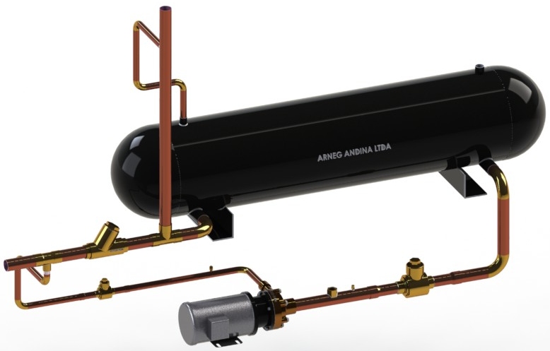
Liquid Pressure Amplification
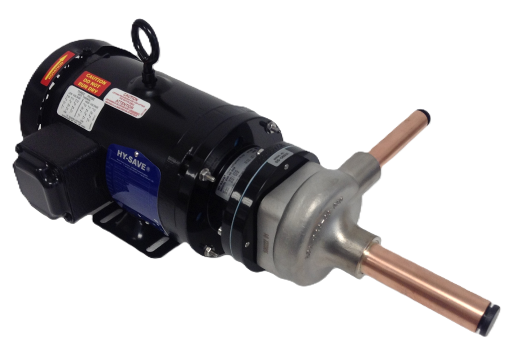
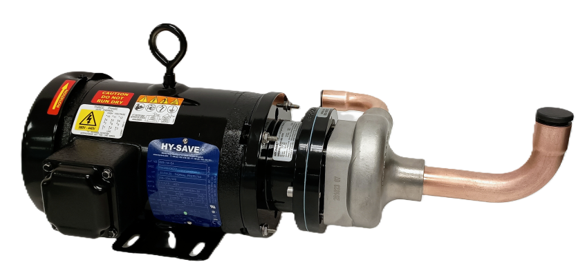
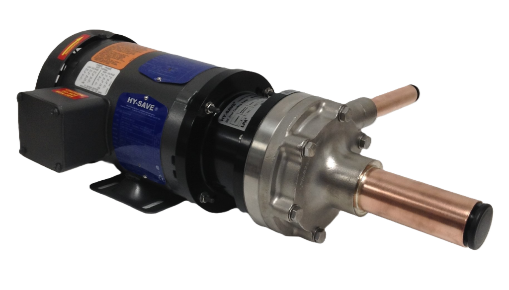
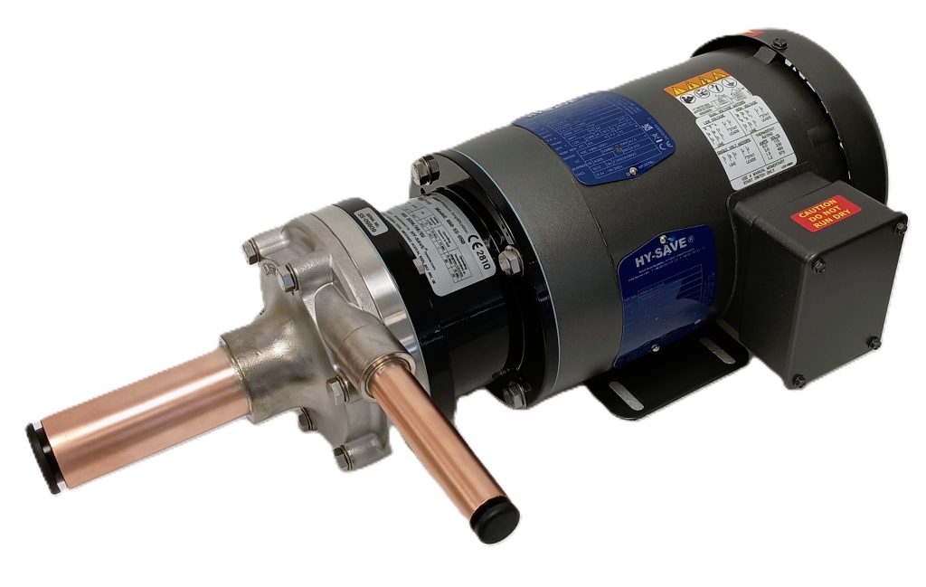
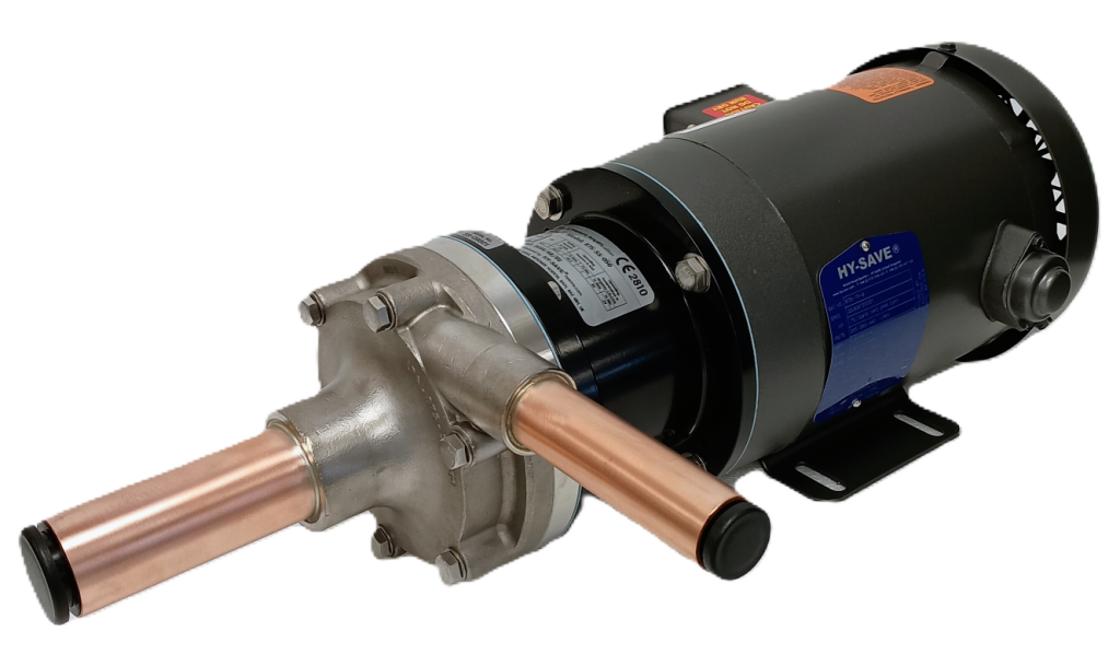
Primarily LPA is about achieving floating head pressures. On DX systems a liquid line pump is added to the liquid line in order to maintain expansion device design operating pressure difference while head pressures is permitted to float with colder ambients. The pump also provides added subcool, by pressure amplification, needed to match the increased saturated refrigerant ∆T/∆P ratio.
Of course, with LPA a small additional charge quantity may be necessary to ensure at least 1K sub-cooling at pump inlet. However, this charge addition is far less than the extra charge needed to achieve required subcool for the same liquid line pressure losses without the use of a pump. The inclusion of a liquid line pump can provide for re-condensing of the liquid line vapor portions mentioned earlier in this article. In addition, it obviously raises liquid pressure, which in most cases acts to re-establish design EEV and TEV pressure drop. The advantage here then is that in many instances the cheaper and more proved TEV could be used in preference to the EEV. A carefully sized capillary can be installed parallel to the TEV to supplement TEV orifice size when design valve pressure drops are still not being achieved. Even when floating head pressures there are still often head pressure constraints requiring head pressure control only at some lower limit. Considering the colder liquids increased saturated ∆T/∆P ratio, head pressure controls cycling in and out can cause a “frothing” of the liquid line again reducing EEV and TEV capacity. The liquid pump will most often clear this liquid line frothing.
Becker/O’Brien, Westfield Estate, Midsomer Norton, UK 2008

